Abstract
The Internet of Everything is bring more automation into our lives. The idea is to allow devices in your home, office, and environment to talk to each other. But behind this idea is the automation of tasks using electronic control. A prime target of automation is the home, one of the lowest tech environments around.
Since automation is coming on strong I thought it would be fun to do some home automation ourselves. So I thought we would begin exploring this new level of automation by building some home automation.
Do you ever get home after work in the spring and notice the inside of the house is hotter than the outside? Well suppose you could sense the temperature outside, and the temperature in the house, and turn on a fan to draw in the cool air before you got home.
We are going to design a system that can do just that and discuss how to program it.
Internet of Things
I would like to take a few minutes and discuss this concept of the Internet of Things, and talk about how it relates to the Maker’s Movement. Here is a definition from Wikipedia.
The Internet of Things (IoT) is the interconnection of uniquely identifiable embedded computing devices within the existing Internet infrastructure. Typically, IoT is expected to offer advanced connectivity of devices, systems, and services that goes beyond machine-to-machine communications (M2M) and covers a variety of protocols, domains, and applications. The interconnection of these embedded devices (including smart objects), is expected to usher in automation in nearly all fields, while also enabling advanced applications like a Smart Grid. Internet of Things.
Let me be clear, I don’t mean that I am focusing this group on making everything internet enabled. But I want you to be aware of how this can be coupled with the things we will discuss.
This group is currently focused on how to harness the Linux programming environment to enable automation using the micro controllers currently on the market. This focus will combine both hardware and software to create interesting devices.
These devices will not be as sophisticated as some commerical products, but will have the advantage of DIY (Do It Yourself). I find DIY both satisfying as home made can be more fun that factory built. It also involves you in the process of expanding your horizons for how to solve a problem. PC computers are great at doing the software tasks, like email, watching movies, balancing your checkbook, or just playing games. But the computer coupled with interface devices can give you a whole new appreciation for the world around you.
The Modern Home
One of the places that automation can have a big impact is in your home. Now there is more to it than speakers in every room and movie distribution. Lets look at a few ideas that could be turned into projects.
Garage Door not very sexy, but have you ever wondered if you closed the door when you left.
Thermostat is ripe for modding. Suppose it knew when you left work to turn up the heat. Or suppose your set back thermostat knew not to set the temperature back since the alarm system was not on.
Lights on the Driveway could turn on when you approached the house, then it could turn on a light on the end of the house when you drove down the driveway. Next it would know it was your car, so it would open your garage door.
The wash is done could be an alarm on your phone, so you knew when to take it out of the washing machine and put it into the dryer.
Your home alarm was triggered would be nice to know if you are not home, and maybe turn on a camera to see it was the cat or a cat burgler.
Do you need more fuel for your furnace? Would it be useful if your system told you when it needed refilling instead of going into the garage to check the tank, or depending on the oil company to remember to fill your tank ontime.
Hopefully you get the idea. Sometimes it can be fun to look around at the devices in your house that you take for granted, and think about how you could improve them. Maybe you are not ready for a robotic lawn mower, but turning on a light in the house when you enter the garage might be nice. Think about it, then make it yourself.
Where to Start
Before we build anything, lets start by defining what it is we want to build. This method of design is similar to what is done when creating any new software or hardware application in a company. We are going to leave out the customer trials, and marketing and pricing, since they do not apply to a DIY project. But otherwise this is a similar simplified process.
I am going to try to show how to arrive at a final design. Along the way we will refine the ideas and discuss the problems. Maybe we will end up with a wholely different solution, or more than one, before we try to implement the problem. For each iteration in the thought process we are going to refer to them as drafts.
Describe the idea
First Draft
We want a system which can measure the outside and inside temperatures around a house, or apartment. Then, when the temperature inside the house is warmer than the temperature outside, and warmer than 72 degrees Fahrenheit, we want to open a window in the house and turn on an exhaust fan to draw in cool air.
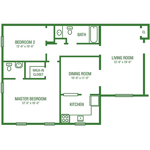
Second Draft
As you can see from the drawing above, we have at lease 3 rooms that we would like to cool. Master Bedroom, Bedroom 2, and Living Room. So we modify the description to include 3 windows that need opening. One in the master bedroom, one in bedroom 2, and one in the living room.
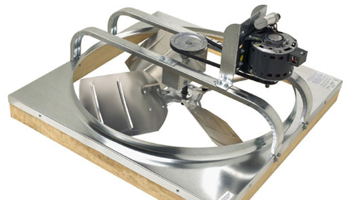
Sincde we will need an exhaust fan, we could look into a ceiling mounted exhaust fan to suck the hot air out of the house and blow it into the attic. These fans are popular since they are large diameter fans that move slowly, but are designed to cool a whole house. We could locate the fan in the hall way between the dining room and the bath room. This would provide a central location and vent the hot air into the attic.
We would probably like to have manual control of the windows and fan so we can override the system if we choose.
So before we try to build somethins lets list our assumptions. These are limitations and design decisions we make to simplfy our software.
Assumptions
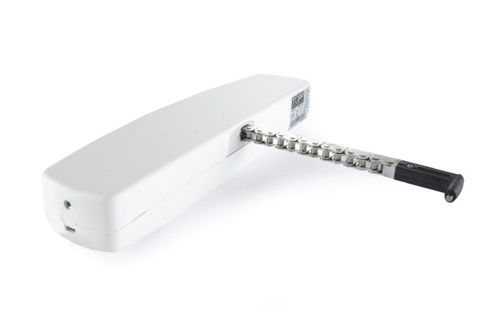
We will assume we can retro fit one window in the living room, one in the master bedroom and one in bedroom 2, with an electric window opener. Additionally we will assume we can open each window by a switch. We will assume we can both open and close a window using a switch.
We will assume we have an attic type exhaust fan. The fan can be switched on or off with a relay.
We will assume that the bedroom doors are left open during the day. This could also be accomplished by having doors which have a louver section to allow air flow through the door.
We will assume you are handy enough to run the wires, and install the fan, window openers, and wiring to a central controller. I am going to make the assumption that you can run wires to each device as opposed to using wireless communication. As a future addition to the system we could add wireless access, but that will add cost and complexity to the design.
We will assume you can setup and program an Arduino micro controller. We will use examples to test the system. Then we can cut and paste the examples into a final program. So you do not need to write all the code from scratch. But we will assume that you are willing to make mistakes and learn from them.
Lets assume you are OK with simple switches and LEDs to monitor and control the system. The Arduino does not talk to a network easily. Again, in the future we could add network connection and a graphical interface. But this will make the program more complex and require additional hardware.
Third Draft
Given the above assumptions lets define the steps that need to be done. In the process we will define the physical, construction, and programming steps needed.
Install an electric window opener on each of the three designated windows. From the window opener we will run a control wire to the Arduino controller.
Install the exhaust fan in the ceiling to draw air out of the house. Run a control wire from the fan to the Arduino controller.
Install a One Wire Digital Temperature Sensor outside the house in the shade. Install one each in the master bedroom, bedroom 2, and the living room. Wire all 4 temperature sensors together and back to the Arduino controller.
Mount the controller box, containing the Arduino, somewhere accessible with 4 push button switches, and 4 led indicators.
Now that we have the hardware defined, lets consider how we are going to design the software for this application.
Each of the electric windows and the fan will be wired into a relay mounted on a circuit board. These relays are operated by the Arduino, but can switch enough power to operate the electric device attached.
For each electric window and the fan we will have an indicator led that turns on when the relay is triggered. There will also be one push button switch next to each led to allow manual control of the relays.
Software Design
For this pass in refining our idea, suppose we try to visualize our design by action and reaction to stimulus.
Turn on the system, set manual control off. Set the state of all the relays to off.
If manual control is off, If the time is after 11 AM and before midnight turn on read temperatures.
If read temperatures is true, and outside temperature is less than living room temperature and more than 72 degrees, open living room window, and turn on fan.
repeat step 3 for master bedroom and bedroom 2.
If manual control button is pressed, toggle manual control on and read temperatures off. Change the state of all the relays to off. Begin manual control loop.
Check the button associated with each relay, If pressed change the state of the relay. Check the state of the manual control button, if it is pressed turn off manual control and return to step 2.
For this part of the design I am going to use what is known as pseudocode. This is like an outline of the code to show what it will do not how to do the operation. Anything after a # is a comment.
# TemperatureActive is a flag to enable or disable temperature check
# TemperatureSleepTime is how long to delay next loop
# SwitchSleepTime is how long to delay next loop
# RTC is value from real time clock

# Check the temperature and make changes as needed
if ( TemperatureActive == true )
then
  if ( TemperatureSleepTime < RTC )
  then
    // read temperatures, and switch relays if needed
    // set TemperatureSleepTime = RTC + 5 minutes
  fi
fi

# Check the switches and make changes as needed
if ( SwitchSleepTime < RTC )
then
  // read switches and set relays if needed
  if ( ManualSwitch == true )
  then
    // change state of TemperatureActive flag
  fi
  set SwitchSleepTime = RTC + 3 seconds
fi

# Check for when to start and end the temperature checks.
if ( RTC == 11:00 AM ) # You might also check manual control
then
  TemperatureActive = true
  TemperatureSleepTime = RTC
fi
if ( RTC == 11:00 PM )
then
  TemperatureActive = false
fi
Construction
Parts List
| Parts Name | Quantity | Source |
|---|---|---|
| Windows Opener assembly | 3 | http://www.window-openers.com/ack4_electric_chain_actuator.html |
| Attic Fan | 1 | |
| Arduino Board | 1 | https://www.sparkfun.com/products/11021 |
| Arduino Power Supply | 1 | http://www.amazon.com/Arduino-9V-1A-Power-Adapter/dp/B00CP1QLSC |
| Real Time Clock | 1 | http://www.adafruit.com/product/264 |
| 4 Power Relay board | 1 | http://yourduino.com/sunshop2/index.php?l=product_detail&p=201 |
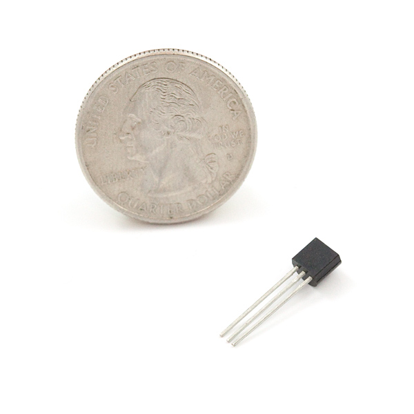
| One Wire Temperature Chips | 4 | https://www.sparkfun.com/products/245 |
| Led Indicators | 5 | |
| momentary switches | 5 | |
| Experimentor’s box | 1 | |
| 3 conductor wire 18 guage | TBD |
First the window openers and fan.
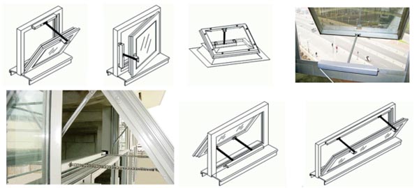
Lets start with the window openers. You should probably use a three conductor wire for these so we can trigger open and closed.
We can mount these openers in any of several configurations.
When it comes to mounting the fan, we should follow the manufacturer’s specifications. It needs to be mounted in a frame in the ceiling. Normally you would mount a set of louvers below it to hide the fan when it is off. The air flow into the fan will open a spring loaded set of louvers.
Temperature Sensors
The next task is to wire the temperature sensors. We want one in each of the three rooms. Since you probably want them out of sight, you might mount them in a corner of the ceiling with a cover over them. You will need three conductor wire since you need +5, ground, and signal wires. But all 4 controllers can be on the same wire. Each sensor has a unique ID to distinguish them.
The Controller Box
For the controller, we are going to mount an arduino in a handy box. In addition to the arduino we will need a Real Time Clock chip.
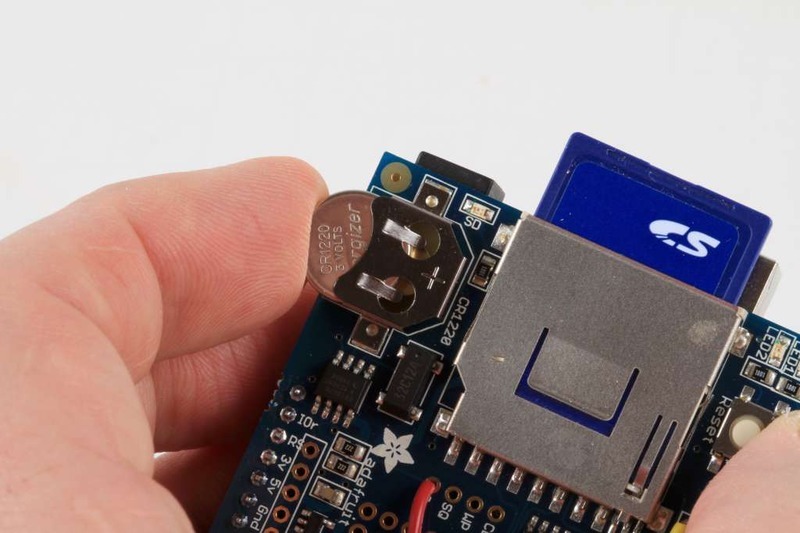
We are going to attach this module to pins Analog 4 and 5 on the back of the board. We will write the programming for this later.
Next we need to attach the relay board to the Arduino.
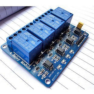
This board needs to be mounted so you can keep access to the contacts. Additionally you will need to use jumper wires from the Arduino to the input connectors on the relay board.
The wiring for the relay board look like this:
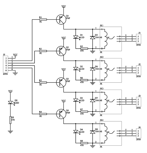
Now the jumpers for the relay board will be
| Arduino Pin | Relay connector |
|---|---|
| 5V | |
| Digital 4 | |
| Digital 5 | |
| Digital 6 | |
| Digital 7 | |
| Gnd | |
The wiring for the windows openers and the fan to the relays I will leave to you. Follow the manufacturer’s directions.
Next we need to conntect the wires from the one wire temperature sensors. Note that all 4 temperature sensors are connected in parallel. So Pins 1, 2, and 3 on all four temperature sensors, are connected to the same wire. This means that there is only one 4.7K ohm wire.
| Arduino Pin | One Wire |
|---|---|
| 5V | |
| 5V | 4.7K ohm |
| 4.7K ohm | |
| Digital 2 | |
| Gnd | |
Next we are going to attach the five momentary switches to the Arduino. These will be used to manually control the relays, and switch into and out of manual control. The switches should be mounted in the cover of the utility box with an LED next to each one. The LEDs for the relays will replace the LEDs on the relay board. The last LED, for the manual control, will go directly to the arduino.
For the switches, one side of the switch will be connected to ground. The other end will be pulled up through a 4.7K ohm resistor and connected to a digital input.
| Arduino Pin | Switch Relay |
|---|---|
| 5V | 4.7K Ohm |
| 8 | Fan |
| 9 | Master Bedroom |
| 10 | Bedroom 2 |
| 11 | Living Room |
| 12 | Manual Toggle |
| Gnd | Switch contact |
For the LEDs, mount them in the cover of the experimenters box one next to each switch. These are wired in parallel with the relays on the power relay board. This will allow you to see which relay is turned on by looking a the outside of the box.
I will presume you know how to hook up a power wall wort to the Arduino.
Drawing of complete control board
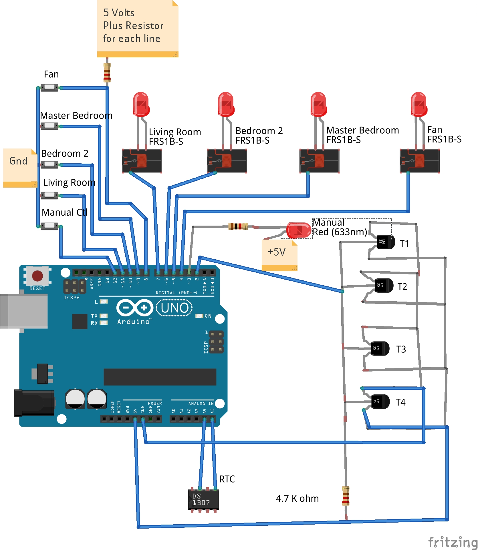
| Label | Part |
|---|---|
| T1 | Outside Temperature |
| T2 | Master Bedroom Temperature |
| T3 | Bedroom 2 Temperature |
| T4 | Living Room Temperature |
Outside of control box
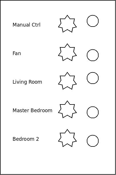
This is a bit crude but the outside of the control box consists of 5 momentary switches, the stars, and 5 LEDs. You should have space to place labels on the box so you remember which button and led go with which relay or control.
Programming the Arduino
Now that we have the hardware configured, it is time to move on to the software.
I am going to assume you already have the programming environment setup for the Arduino. If this is not the case I suggest you go to Getting Started with Arduino to setup your computer. If you have never programmed an Arduino before, you might want to look at Examples. I recommend you try out Basic and Digital examples before you proceed.
Before we start these tests, be sure to disconnect the control wires from the fan and the 3 window openers. Once we know that the control box is working we will be ready to reconnect the control wires and test them separately. But first we want to make sure the control box is correct without the possibility of damaging any of the more expensive hardware. You have been warned.
Testing the RTC
We are going to spend some time using the article DS1307-RealTime-Clock-Brick to give us a basic working knowledge of how to use the RTC (Real Time Clock).
The basic idea behind a RTC is to count the number of seconds since January 1st 1970. This number can then be converted into the time and date using some math functions.
We are going to use the RTC for timing. We want to sleep for 2 minutes, so we can take the value of RTC, and add 120 to it for 2 minutes in the future.
Testing the temperature sensors
Next we are going to learn how to use the one-wire temperature sensors. For this learning process we will use Arduino 1-Wire Tutorial to learn about how to read and work with these temperature sensors. The devices are fairly simple to program once you have set them up correctly.
Each device has a unique address which is how you identify them. The process of converting the temperature is handled by the library.
Testing the relays
For the relay board we are going to test that we can drive the relays on and off. Even though we could hook up a circuit to the relay contacts for this test, instead we will watch the LEDs to indicate which relay is on and off.
We will use the tutorial at Arduino Power ! to test the relays. But we will make the following changes to the sketch since our relay control wiring is not in the same place they specify.
#define Relay_1  4  // Arduino Digital I/O pin number
#define Relay_2  5
#define Relay_3  6
#define Relay_4  7
#define Manual   8
Test the switches
The last test step is to see if we have hooked up the switches correctly. For this test I am going to rewrite part of the relay test. When you press a button it will move a digital pin low which will toggle the state of one of the relays.
/*-----( Declare Constants )-----*/
int relayPin = 4; // Relay connected to digital pin 4
int switchPin = 8;   // pushbutton connected to digital pin 8
int val = 0;     // variable to store the read value

/*----( Setup of controls )------*/
void setup()
{
    pinMode(relayPin, OUTPUT);      // sets the digital pin 8 as output
    pinMode(switchPin, INPUT);      // sets the digital pin 8 as input
    // start serial port
    Serial.begin(57600);
}

/*------------( Main part of program )----------*/
void loop()
{
    val = digitalRead(switchPin);   // read the input pin
    digitalWrite(relayPin, val);    // sets the relay to the button's value
    Serial.print("Switch: ");
    Serial.print(val);
    Serial.print("\n\r");
    delay(2000);
}
The complete program
Now that we have tested all the components, it is time to put it all together.
I am going to try to include all the code to do the whole job. During the testing we have run several tests which included libraries and code designed to test the individual pieces of the design.
To make the complete program I am going to cut out pieces of the individual test programs and combine them into one piece of code. You could test this system to see how it works without hooking up the wires from the relays to the actual devices.
I considered including the program, but I thought it might be more interesting to create the program during the talk. But I thought I would sketch out some ideas to help move things along
// Includes for the libraries go first
#include <OneWire.h>
#include <DallasTemperature.h>
#include <Wire.h>
#include "RTClib.h"

// Definitions follow for RTC
RTC_DS1307 RTC;

// Data wire is plugged into pin 3 on the Arduino
#define ONE_WIRE_BUS 3

// Setup a oneWire instance to communicate with any OneWire devices
OneWire oneWire(ONE_WIRE_BUS);

// Pass our oneWire reference to Dallas Temperature.
DallasTemperature sensors(&oneWire);

// Assign the addresses of your 1-Wire temp sensors.
// See the tutorial on how to obtain these addresses:
// http://www.hacktronics.com/Tutorials/arduino-1-wire-address-finder.html

// the device address will look something like { 0x28, 0x94, 0xE2, 0xDF, 0x02, 0x00, 0x00, 0xFE };
DeviceAddress OutsideTemp       = { };
DeviceAddress MasterBedroomTemp = { };
DeviceAddress Bedroom2Temp      = { };
DeviceAddress LivingRoomTemp    = { };

// storage of temperature data
float OutsideTempValue;
float MasterBedroomTempValue;
float Bedroom2TempValue;
float LivingRoomTempValue;

/*-----( Declare Variables )-----*/
int ManualLED          = 3;  // Drive for manual LED
int FanRelay           = 4;  // Arduino Digital I/O pin number for relays
int MasterBedroomRelay = 5;
int Bedroom2Relay      = 6;
int LivingRoomRelay    = 7;

int FanSwitch           = 8;  // Arduino Digital I/O pin number for the switches
int MasterBedroomSwitch = 9;
int Bedroom2Switch      = 10;
int LivingRoomSwitch    = 11;
int ManualSwitch        = 12;

/*-------( Define variables to hold the relay state )-----*/
int FanRelayState = RELAYOFF;
int MasterBedroomRelayState = RELAYOFF;
int Bedroom2RelayState = RELAYOFF;
int LivingRoomRelayState = RELAYOFF;

// Program Variables
boolean TemperatureActive = false;
DateTime TemperatureSleepTime;
DateTime SwitchSleepTime;

#define RELAYON 1
#define RELAYOFF 0

void setup () {
    // Initialization of RTC
    Serial.begin(57600);
    Wire.begin();
    RTC.begin();
    // set the arduino clock from your computer.
    RTC.adjust(DateTime(__DATE__, __TIME__));

    // Start up the library
    sensors.begin();
    // set the resolution to 10 bit (good enough?)
    sensors.setResolution(OutsideTemp, 10);
    sensors.setResolution(MasterBedroomTemp, 10);
    sensors.setResolution(Bedroom2Temp, 10);
    sensors.setResolution(LivingRoomTemp, 10);

    //-------( Initialize the relay pins )--------
    pinMode( ManualLED, OUTPUT );
    pinMode( FanRelay, OUTPUT );
    pinMode( MasterBedroomRelay, OUTPUT );
    pinMode( Bedroom2Relay, OUTPUT );
    pinMode( LivingRoomRelay, OUTPUT );

    //-------( Initialize the switch pins )----------
    pinMode( FanSwitch, INPUT );
    pinMode( MasterBedroomSwitch, INPUT );
    pinMode( Bedroom2Switch, INPUT );
    pinMode( LivingRoomSwitch, INPUT );
    pinMode( ManualSwitch, INPUT );

    //-------( Initialize Relay states )-----------
    FanRelayState = RELAYOFF;
    MasterBedroomRelayState = RELAYOFF;
    Bedroom2RelayState = RELAYOFF;
    LivingRoomRelayState = RELAYOFF;

    //-------( Initialize Pins so relays are inactive at reset)----
    digitalWrite(FanRelay, FanRelayState);
    digitalWrite(MasterBedroomRelay, MasterBedroomRelayState);
    digitalWrite(Bedroom2Relay, Bedroom2RelayState);
    digitalWrite(LivingRoomRelay, LivingRoomRelayState);

}

//--( Function to switch the state of the relay )--
int switch_state( int Relay_state, int Relay_pin )
{
  if ( Relay_state == RELAYOFF )
  {
    digitalWrite( Relay_pin, RELAYON );
    return RELAYON;
  }
  else
  {
    digitalWrite( Relay_pin, RELAYOFF );
    return RELAYOFF;
  }
}

// Convert temperature to Farenheiy
void convert_farenheit ()
{
    float tempC;
    tempC = sensors.getTempC( OutsideTemp );
    OutsideTempValue = DallasTemperature::toFahrenheit(tempC);
    tempC = sensors.getTempC( MasterBedroomTemp );
    MasterBedroomTempValue = DallasTemperature::toFahrenheit(tempC);
    tempC = sensors.getTempC( Bedroom2Temp );
    Bedroom2TempValue = DallasTemperature::toFahrenheit(tempC);
    tempC = sensors.getTempC( LivingRoomTemp );
    LivingRoomTempValue = DallasTemperature::toFahrenheit(tempC);

}

// Main loop
void loop ()
{

   //----------( Read the RTC variable now )-----------------
   DateTime now = RTC.now();

   //----------( Compare the temperatures and switch the relays )-------------
   if ( TemperatureActive == true )
   {
      if ( TemperatureSleepTime < now.unixtime() )
      {
          // Read temperatures and switch relays as needed
          convert_fareheit();

          if ((  OutsideTempValue >= 72 ) && (( OutsideTempValue + 2 ) < MasterBedroomTempValue ))
          {
              MasterBedroomRelayState = RELAYON;
              digitalWrite( MasterBedroomRelay, MasterBedroomRelayState );
              if ( FanRelayState == RELAYOFF )
              {
                  FanRelayState = RELAYNO;
                  digitalWrite( FanRelay, FanRelayState );
              }
          }

          if ((  OutsideTempValue >= 72 ) && (( OutsideTempValue + 2 ) < LivingRoomTempValue ))
          {
              LivingRoomRelayState = RELAYON;
              digitalWrite( LivingRoomRelay, LivingRoomRelayState );
              if ( FanRelayState == RELAYOFF )
              {
                  FanRelayState = RELAYNO;
                  digitalWrite( FanRelay, FanRelayState );
              }
          }

          if ((  OutsideTempValue >= 72 ) && (( OutsideTempValue + 2 ) < Bedroom2TempValue ))
          {
              Bedroom2RelayState = RELAYON;
              digitalWrite( BedRoom2Relay, Bedroom2RelayState );
              if ( FanRelayState == RELAYOFF )
              {
                  FanRelayState = RELAYNO;
                  digitalWrite( FanRelay, FanRelayState );
              }
          }


          TemperatureSleepTime = ( now.unixtime() + 300 );
      }
   }

   //---------( Check the Switches and switch as required )----------
   if ( SwitchSleepTime < now.unixtime() )
   {
       // read switches and change state of relays
       val = digitalRead( FanSwitch);
       if ( val == 0 )
       {
           FanRelayState = switch_state( FanRelayState, FanRelay );
       }
       val = digitalRead( MasterBedroomSwitch);
       if ( val == 0 )
       {
           MasterBedroomRelayState = switch_state( MasterBedroomRelayState, MasterBedroomRelay );
       }
       val = digitalRead( Bedroom2Switch);
       if ( val == 0 )
       {
           Bedroom2RelayState = switch_state( Bedroom2RelayState, Bedroom2Relay );
       }
       val = digitalRead( LivingRoomSwitch);
       if ( val == 0 )
       {
           LivingRoomRelayState = switch_state( LivingRoomRelayState, LivingRoomRelay );
       }

       // If manual switch is low
       val = digitalRead( MamualSwitch);
       if ( val == 0 )
       {
           if ( TemperatureActive == true )
           {
               digitalWrite(ManualLED, 1);
               TemperatureActive = false;
           }
           else
           {
               digitalWrite(ManualLED, 1);
               TemperatureActive = true;
           }
       }
   }

   // Is it time to turm on the Temperature measuring
   if ( ( now.hour() == 11 ) && ( now.minute() == 0 ) )
   {
      TemperatureActive = true;
      TemperatureSleepTime = now.unixtime() ;
   }

   // Is it time to turm off the Temperature measuring
   if ( ( now.hour() == 23 ) && ( now.minute() == 0 ) )
   {
      TemperatureActive = false;
   }

}
TBD
This is the code I wrote. I have not run it, nor debugged it. There are probably mistakes, so if you find some errors let me know and I will correct them.
This was an exercise in how to start with an idea for home automation, and bring it to fruition. You needed to have both construction skills and programming skills to pull it off, but that is part of the fun.
This system only does a simple automation trick, and does not have any interface other than the buttons and LEDs. But it is reasonably complete, even if the code needs more work.
Purchasing some parts and exploring ideas can be a great way to get involved in the maker movement. But it can also be fun for anyone. So here are a few sites I recommend to get started. Remember the Arduino is only one controller, there are others we will explore.
Sites for DIY experimenters
SparkFun is an online retail store that sells the bits and pieces to make your electronics projects possible. No matter what your vision is, our products and resources are designed to make the world of electronics more accessible to the average person. In addition to products, SparkFun, through our Department of Education, offers classes and online tutorials designed to help educate individuals in the wonderful world of embedded electronics. Our ever-growing product catalog boasts over 3,500 components and widgets designed to help you unleash your inner inventor. About Sparkfun
Adafruit was founded in 2005 by MIT engineer, Limor “Ladyada” Fried. Her goal was to create the best place online for learning electronics and making the best designed products for makers of all ages and skill levels. Adafruit has grown to over 50 employees in the heart of NYC with a 15,000+ sq ft. factory. Adafruit has expanded offerings to include tools, equipment and electronics that Limor personally selects, tests and approves before going in to the Adafruit store. Limor was the first female engineer on the cover of WIRED magazine and was recently awarded Entrepreneur magazine’s Entrepreneur of the year. In 2014 Adafruit was ranked #11 in the top 20 USA manufacturing companies and #1 in New York City by Inc. 5000 “fastest growing private companies”. About Us
List your project ideas. This can be helpful for both the novice and the experienced.
This intro seems too brief for the Arduino Playground, but in reality it contains dozens of projects from Easy, chlonos a talking clock, to Arduino Smart phone Demo.
Our Story
The seeds of Instructables germinated at the MIT Media Lab as the future founders of Squid Labs built places to share their projects, connect with others, and make an impact on the world. One of these early places was a blog Zeroprestige, which was an open source hardware experiment for kitesurfing. Here they documented their hand-sewn kites, plywood boards, and other general mayhem that happens when PhDs and high winds collide.
“As a result of freely sharing our work, we met a ton of great people, received great opportunities, and were smacked in the face with the need for a web-based documentation system.”
Instructables became that documentation system in 2005, as an in-house project of Squid Labs. When they weren’t solving interesting problems like solar panels for driveways, efficiently harnessing human power, or strain sensing ropes, you could find them sharing Instructables from the workshop. From cooking to 3d printing, to making just about anything fly, Instructables became the recipient of countless hours of tinkering, soldering, stitching, frying, and fun, making just about anything.
Instructables was officially spun out of Squid Labs in the summer of 2006, and has gone on to grow from a modest hundreds of projects to over one hundred thousand. The community that now calls the site home, is an amazing mix of wonder from around the world. Every day we continue to be amazed by the imagination, curiosity, and simple awesomeness of everyone who shares their creations with us on Instructables. Our Story
Written by John F. Moore
Last Revised: Fri Jan 30 01:16:28 PM EST 2026

This work is licensed under a Creative Commons Attribution-NonCommercial-ShareAlike 3.0 Unported License.