Table of Contents
Abstract
This is the second of three talks about How Does a Computer work. This talk will discuss the CPU.
For this talk we will focus on the computing engine in the computer.
History of the Transistor
Before the transistor there was the vaccuum tube.
Vaccuum Tube
When we think of how a computer works, we often think of the transistor. The transistor is a type of amplifier or switch where a voltage controls the flow of electrons between two points. But before the transistor people use vaccuum tubes as switches.
Lets look at a vaccuum tube to understand how a switch works.
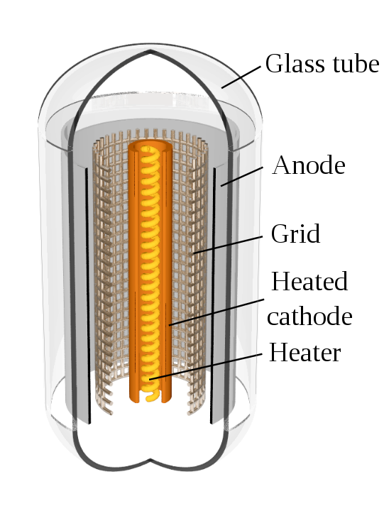
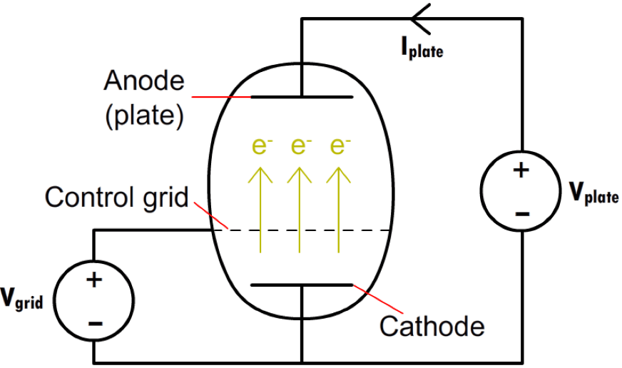
The triode works by heating the cathode which causes the electrons to jump from the cathode to the anode. But between these two plates is a grid. A voltage applied to the grid can lessen or increase the flow of electrons to the anode.
Enter the Transistor
Now that we see how an electronic circuit can be used to amplify a signal, lets move on to the transistor.
Austro-Hungarian physicist Julius Edgar Lilienfeld patented a field-effect transistor in 1926,[1] but it was not possible to actually construct a working device at that time. The first practically implemented device was a point-contact transistor invented in 1947 by American physicists John Bardeen, Walter Brattain, and William Shockley at Bell Labs. Bardeen, Brattain, and Shockley shared the 1956 Nobel Prize in Physics for their achievement.Transistor
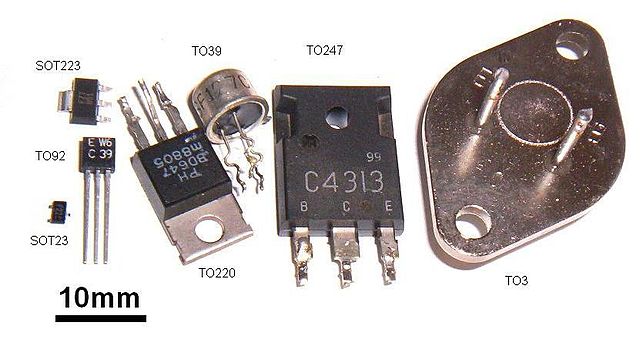
The transistor used a silicon wafer so it was much smaller and more power efficiant than the vaccuum tube. Once the manufacturing process for transistors was rolling, the cost of using transistors fell.
.jpg)
Not only was the transistor much smaller than the vaccuum tube, but it leant itself to creating multiple transistors on a single wafer of silicon.
Early concepts of an integrated circuit go back to 1949, when German engineer Werner Jacobi[4] (Siemens AG)[5] filed a patent for an integrated-circuit-like semiconductor amplifying device[6] showing five transistors on a common substrate in a 3-stage amplifier arrangement. Integrated circuit
We can now see how the transistor lead to the integrated circuit. Once we were able to create multiple transistors on a single wafer, we have the structure to create more complex circuits.
So now we have a switch that can control the flow of electricity. So we next need to decide how we are going to use the transistors.
Enter Binary
OK so now we have a method of using the on and off of the transistor to convey data. But how do we do that?
Boolean Algerbra and Logic Gates
The CPU
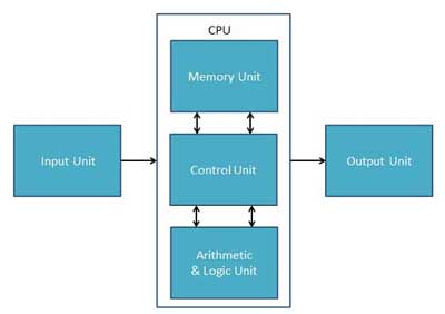
Memory or Storage Unit
Also known as Registers.
This unit can store instructions, data, and intermediate results. This unit supplies information to other units of the computer when needed. It is also known as internal storage unit or the main memory or the primary storage or Random Access Memory (RAM).
Its size affects speed, power, and capability. Primary memory and secondary memory are two types of memories in the computer. Functions of the memory unit are −
It stores all the data and the instructions required for processing.
It stores intermediate results of processing.
It stores the final results of processing before these results are released to an output device.
All inputs and outputs are transmitted through the main memory.
Control Unit
This unit controls the operations of all parts of the computer but does not carry out any actual data processing operations.
Functions of this unit are −
It is responsible for controlling the transfer of data and instructions among other units of a computer.
It manages and coordinates all the units of the computer.
It obtains the instructions from the memory, interprets them, and directs the operation of the computer.
It communicates with Input/Output devices for transfer of data or results from storage.
It does not process or store data.
ALU (Arithmetic Logic Unit)
This unit consists of two subsections namely,
Arithmetic Section
Function of arithmetic section is to perform arithmetic operations like addition, subtraction, multiplication, and division. All complex operations are done by making repetitive use of the above operations.
Logic Section
Function of logic section is to perform logic operations such as comparing, selecting, matching, and merging of data.
Source of info Computer - CPU(Central Processing Unit)
The Four Primary Functions of the CPU
The CPU processes instructions it receives in the process of decoding data. In processing this data, the CPU performs four basic steps:
Fetch: Each instruction is stored in memory and has its own address. The processor takes this address number from the program counter, which is responsible for tracking which instructions the CPU should execute next.
Decode: All programs to be executed are translated to into Assembly instructions. Assembly code must be decoded into binary instructions, which are understandable to your CPU. This step is called decoding.
Execute: While executing instructions the CPU can do one of three things: Do calculations with its ALU, move data from one memory location to another, or jump to a different address.
Store: The CPU must give feedback after executing an instruction, and the output data is written to the memory.
Fetch, Decode, and Execute Cycle
Example CPUs
First lets look at an older CPU with a simple pin structure.
Motorola 6800
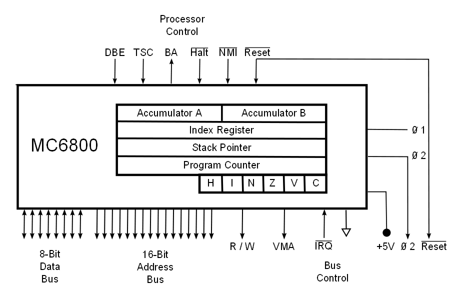
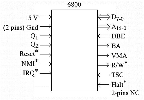
Now let us see the Pin functions of the M6800 microprocessor.
|
Pins |
Type |
Function |
|---|---|---|
|
A15– A0 |
Output |
16-bit address bus, which provides the addresses for memory (up to 64KB) |
|
D7– D0 |
Input/Output |
8-bit bi-directional data bus to transfer data between memory/IO devices and CPU. |
|
Vcc |
Input |
It is Power Supply Pin of M6800. It uses DC power supply of +5V |
|
GND |
Input |
There are two ground pins (Pin number 1 and 21), both are connected with the ground |
| HALT |
Input |
The Halt Pin is active low, input pin. When it is activated, the CPU goes to the halting state. In this state, the address bus, and the data bus, and also R/W the go-to high impedance state. |
|
φ1 and φ2 |
Input |
These are basically two-phase clock inputs. It needs a clock generator chip M6870 to provide a two-phase clock. The typical operating frequency is 1MHz and the minimum frequency is 100KHz. |
|
IRQ |
Input |
This pin is for an Interrupt request. It can be masked or disabled. |
|
TSC |
Input |
It is an active high input pin. It is translated Control pin. This pin is like the hold input of Intel8085 Microprocessor. |
|
BA |
Output |
It is another Active high output pin. BA stands for Bus Available. In 8085, there is HLDA pin, which is similar to the BA pin of M6800. |
|
R/W |
Output |
This is active low output pin. TheCPU sends 1 in this pin, when it tries to read the data, and sends 0, when tries to write data to the memory. |
| NMI |
Input |
This is active low Non-Maskable Interrupt pin. |
| RESET |
Input |
It is active low input pin. When low signal is passed the M6800 is reset. |
|
VMA |
Output |
VMA is active high output pin. It is valid Memory Access. When the pin is activated, it indicates that the address bus is holding a valid address. It is activated a little after the address is send via address bus. |
|
DBE |
Input |
DBE is active high Input pin. The name suggests Data Bus Enable.So, when this pin is high, either the data are coming out from the data bus or going in through the data bus. But when it islow, it means the data bus pins are in tristate condition.Generally it is connected to pin. |
|
NC |
—- |
The NC are NoConnection. In this clip, there are two NC pins |
Source: Pin description of 6800
For more information consult the 6800 Specs
Intel Pentium
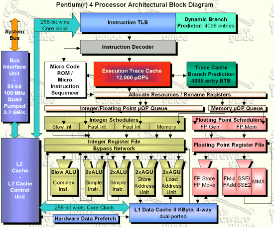
I decided not to copy over the specs, but they are available as Pentium Specs
Written by John F. Moore
Last Revised: Tue 01 Sep 2020 08:10:13 PM EDT

This work is licensed under a Creative Commons Attribution-NonCommercial-ShareAlike 3.0 Unported License.
