Abstract
How is electricity generated? What is the relationship between magnets and electricity as used in motors and generators? We will discuss how electricity gets to our homes. Lastly we will discuss the terminology for electricity.
Special Note
I was informed today Monday 12 Oct. 2020 that Anthony Tedesco had also given a talk about electricity on 8 Oct. 2020. After looking at his talk, available to members, Electricity: All around us, I am still going to offer this talk as written, but I will point out where Anthony has discussed some point better than me. Some of the information will be similar, but some of it will complement his talk. So to Anthony, I apologize for having a similar talk but I think these two talks will complement each other.
What is electricity and how is it created.
Electricity consists of WHAT?
I think we should begin with understanding where does electricity come from. First we will see what electricity is.
So we now can see that electricity comes from the movement of electrons through conductors. We can also see how to prevent electrons from flowing via the use of an insulator.
How Magnets Produce Electricity
This is a very old video but it explains how electricity is created using magnets and wires. So excuse the somewhat dated presentation, but it is interesting how it is presented.
So now we have seen how a magnet moving over a conductor can create a flow of electrons. This is the basic principle of electric generation.
Electricity creates a Magnet
We have seen how to use a magnet to create an electric current. But suppose you have an electric current and want to create a magnet. Lets see.
Now we can see that the flow of electricity can be used to create a magnet. This connection between a magnet and a flow of electrons is both interesting and useful as we will see.
How an AC generator produces electricity
Now that we understand how to create an electric current with a magnet, lets see how a generator produces electricity. AC generators are what the utility company uses to create the power for your home or apartment.
A galvanometer is just a meter which indicates the flow of electrons from zero either positive or negative. An Electromotive force for our purposes is the voltage. We will go into these terms later.
How a DC Electric Motor works
Now that we have seen how a generator creates a flow of electricity, lets see how electricity in a motor can create motion from an electric current.
Did anyone notice how similar the DC motor was to the generator? Lets confirm our suspicion.
Electric Motor vs Electric Generator
I find this ability of turning a generator into a motor or a motor into a generator interesting. This is the basis of how electric cars accelerate and brake. But we will come back to this topic in a later talk.
How electricity gets from a Power plant to your outlet
So we have seen how a generator works. Most generation is done in a large power plant located away from populated areas. To get the power from the Generator to the consumer we need the electric grid.
Electric Grid
Now that we see the components we will look at how electricity is stepped up and down for transmission over the grid and to our homes.
How a transformer Works
Fuses, Circuit breakers, Electric Panels
One important element in any electric circuit is preventing too much current from flowing through a given wire.
Fuse
In electronics and electrical engineering, a fuse is an electrical safety device that operates to provide overcurrent protection of an electrical circuit. Its essential component is a metal wire or strip that melts when too much current flows through it, thereby stopping or interrupting the current. It is a sacrificial device; once a fuse has operated it is an open circuit, it must be replaced or rewired, depending on type. Fuse (electrical)
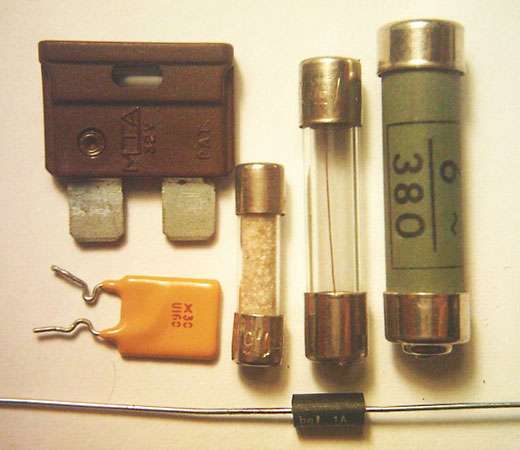
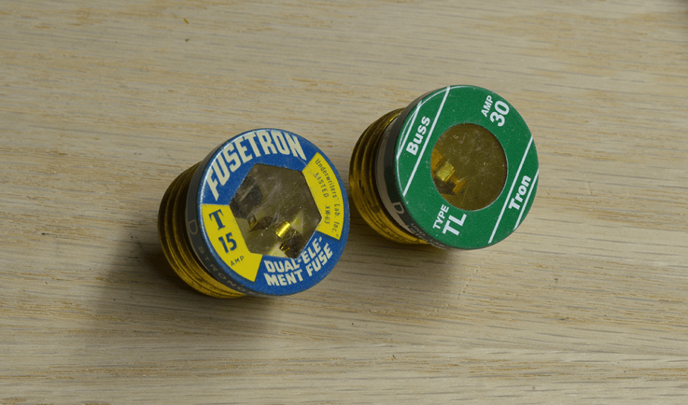
Most of the time today, we see fuses in small electric devices, but seldomly in a home. How ever some older homes have fuses that look like this.
Circuit Breakers
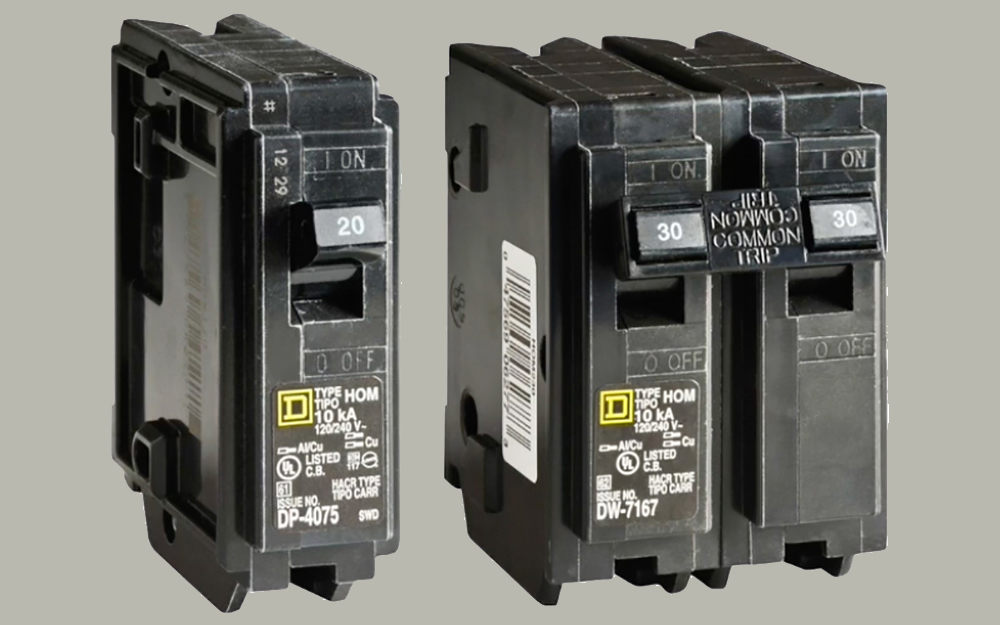
A circuit breaker is an automatically operated electrical switch designed to protect an electrical circuit from damage caused by excess current from an overload or short circuit. Its basic function is to interrupt current flow after a fault is detected. Unlike a fuse, which operates once and then must be replaced, a circuit breaker can be reset (either manually or automatically) to resume normal operation. Circuit Breaker
Today most living spaces use circuit breakers. They are better than fuses because they can be reset once the short is removed, instead of needing replacement.
Electric Panels
North American distribution boards are typically housed in sheet metal enclosures, with the circuit breakers positioned in two columns operable from the front. Some panelboards are provided with a door covering the breaker switch handles, but all are constructed with a dead front; that is to say the front of the enclosure (whether it has a door or not) prevents the operator of the circuit breakers from contacting live electrical parts within. Busbars carry the current from incoming line (hot) conductors to the breakers, which are secured to the bus with either a bolt-on connection (using a threaded screw) or a plug-in connection using a retaining clip. distribution board (also known as panelboard, breaker panel, or electric panel)
This is where the electricity from the outside is distributed to different parts of the house or apartment. The circuit breakers connect from a common power bus to individual wires in the house.
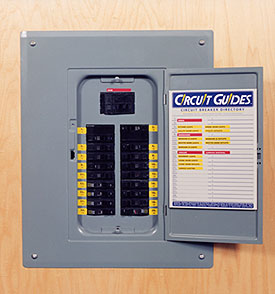
Lets have a look at a circuit panel with the cover removed.
BreakerpanelInnards.jpg)
House Wiring
Electricity into the House
We are now going to consult a couple of interesting web pages I found while I explain some things using the drawings on the pages.
3 phase explained
I want you to understand a little about phases. The purpose is to see how we get 120 and 208 voltage in the house.
What is 3-phase electric/ Power transmission from generator to end user
Electric Measurements
Now that we see how we get our electricity lets talk about how we measure electricity. There are a few basic ideas needed.
What is an Amp?
So we now see that 1 amp is a specific measure of electron flow.
What is a Volt?
So basically voltage is the pressure that makes the atoms move and amps is a measure of the number of electrons.
What is a Watt?
Now we the explanation for most of the terms we need to understand electricity. But there are a few more terms and then some math to round things out.
Tying it all together
OK, lets step back and discuss how the terms relate to each other.
Watts, Kilowatts, and Kilowatt hours
The concept of a watt is the amount of electrical work done. It is measured in Watts. We can calculate watts by multiplying the Voltage by the amperage.
Watt = Volts X Amps
You have probably heard the term from your electric company of Kilowatt hour {kWh). Con Edison defines it as
We measure your electricity by how many kilowatt hours (kWh) you use. One kWh will light a 100 watt bulb for 10 hours.
Resistance
When we want to restrict the flow of amps through a device we use a resistance. This can be in the form of a device the slows down the flow of electrons as in an incandescent light. Or it can be resisting the flow of electrons by producing work, such as a motor. Resistance is measured in Ohms
Ohms = Voltage / amps
For example if a light is 40 watts, and the voltage is 120 volts. Can we find the amount of amps needed?
Watts = volts X Amps or Amps = watts / volts
40 watts / 120 volts = 0.33 amps
Now that we know the voltage and the amps we can figure out the resistance of the 40 watt bulb by
Ohms = Volts / amps
Suppose we know the voltage is 120 volts, and the current is 0.33 amps. What is the resistance?
120 volts / 0.33 amps = 363.63 Ohms
Now lets check our work by seeing if the values match
Volts = amps X ohms
0.33 amps X 363 ohms = 119.73 volts
Pretty close. We will return to some of these terms when we discuss the wiring in the home and troubleshooting.
Written by John F. Moore
Last Revised: Sun Jan 28 03:45:14 PM EST 2024

This work is licensed under a Creative Commons Attribution-NonCommercial-ShareAlike 3.0 Unported License.